Table Of Content

If each student must enroll in a course, the participation of students will be total. Total participation is shown by a double line in the ER diagram. Defines the numerical attributes of the relationship between two entities or entity sets.
Types of Entity Relationship Diagrams
IE notation uses Crow's foot to express cardinality (one to many relationship) instead of Chen's notation to epxress the same. If you find it difficult to get started with drawing an ER diagram, don't worry. Try to follow the steps below to understand how to draw an ER diagram effectively. The figure below shows an example of a one-to-many relationship.
Cardinality Types
ER model helps to systematically analyze data requirements to produce a well-designed database. The ER Model represents real-world entities and the relationships between them. Creating an ER Model in DBMS is considered as a best practice before implementing your database. Use the import feature within our ER diagram tool to connect to your DBMS and upload your database tables and schemas directly into Lucidchart. You can then drag your tables directly onto the canvas, and Lucidchart will automatically draw lines between entities based on the relationships in your database structure. Today, ER diagrams are still widely used in software engineering and database design.
ER diagram tool
If an attribute can have more than one value it is called a multi valued attribute. It is important to note that this is different from an attribute having its own attributes. For example, a teacher entity can have multiple subject values. An entity can be a person, place, event, or object that is relevant to a given system. For example, a school system may include students, teachers, major courses, subjects, fees, and other items.
Cardinality
Over all, we can say that it is a great alternative for paid tools, especially if you are just a casual user. ER diagrams have trouble showing certain kinds of relationships or rules well. For example, really complicated structures or rules about time or space can be hard to draw accurately using ER diagrams. For example, the entity “Carpenter” may be related to the entity “table” by the relationship “builds” or “makes”. Relationships are represented by diamond shapes and are labeled using verbs.

Construct Conceptual, Logical and Physical ER Model
A database view is the result of a query on the data stored in a database. You can select columns, specify where and join statements to a view and present the data as if the data were coming from one single table. With Visual Paradigm's ERD tool, you can edit database view in a visual editor. Attributes are the properties or characteristics of an entity; they hold its data. For example, a Student entity could have attributes like Student_ID, First_Name, Last_Name, and Email. Each attribute of an entity becomes a column in a table in the database.
Logical Data Model
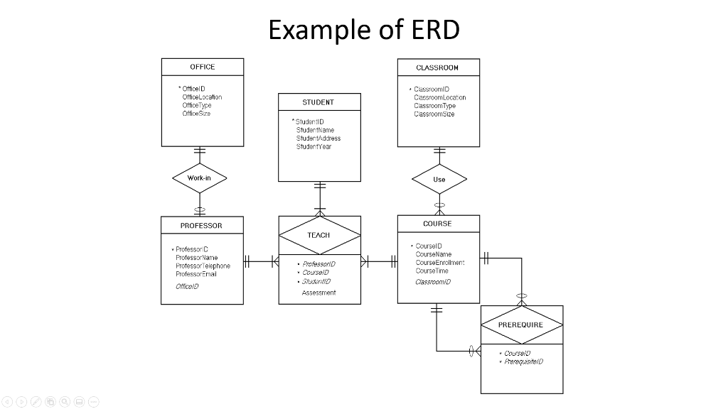
Rectangles that represent entities, ovals that represent the attributes of entities, and diamonds for describing the relationship between entitities. In SmartDraw, choose the Automatic ERD (Database Diagram) in the Extension section of the template dialog. When prompted import the CSV file with your table definitions. Select the columns and types you want to visualize and click "Build Diagram". The database diagram generated is going to be fully editable.
What is ER Diagram?
It is also perfectly suited for development teams because of its strong support for collaboration. It takes time and effort to develop a data model with ERD. A helpful database design tool should be able to reduce your time and effort spent. Visual Paradigm provides you with not only an ERD tool but also a set of visual modeling features that helps you draw faster and easier. It supports most of the popular relational database management systems in the market today both in terms of database design, database generation, and ERD reversal. The relationship between the weak entity type and its identifying strong entity type is called identifying relationship and it is represented by a double diamond.
Uses of entity relationship diagrams
Jiang Qiong Er Steps Onto the Milan Design Scene After Shang Xia - Yahoo Movies Canada
Jiang Qiong Er Steps Onto the Milan Design Scene After Shang Xia.
Posted: Thu, 11 Apr 2024 07:00:00 GMT [source]
Entities are the main objects or concepts represented in a database. They are usually distinguishable real-world objects or abstractions of real-world objects or concepts. For example, in a university database, the entities could be Students, Courses, and Teachers. Each entity in the data model will become a table in the final database. A logical ER model is developed to enrich a conceptual model by defining explicitly the columns in each entity and introducing operational and transactional entities.
Cardinality is the mathematical sense just means the number of values in a set. In relationship to databases and ERD, cardinality specifies how many instances of an entity relate to one instance of another entity. While cardinality specifies the occurrences of a relationship, ordinality describes the relationship as either mandatory or optional. In other words, cardinality specifies the maximum number of relationships and ordinality specifies the absolute minimum number of relationships. They will also differ in how they display entities and their attributes and whether or not they show relationships or attributes as separate symbols. In business process mapping, BPMN Business Process Diagram (BPD) can be drawn to visualize business workflows.
Lucidchart is an intelligent diagramming solution with the tools to help you create an ER diagram online in minutes. ER diagrams constitute a very useful framework for creating and manipulating databases. First, ER diagrams are easy to understand and do not require a person to undergo extensive training to be able to work with it efficiently and accurately.


No comments:
Post a Comment